Circuit Diagram Abbreviation

Abbreviations For Electrical Symbols Yahoo Image Search

Circuit Diagram Abbreviations Wiring Diagram
Components Code And Abbreviation On Schematic Diagram Metua365

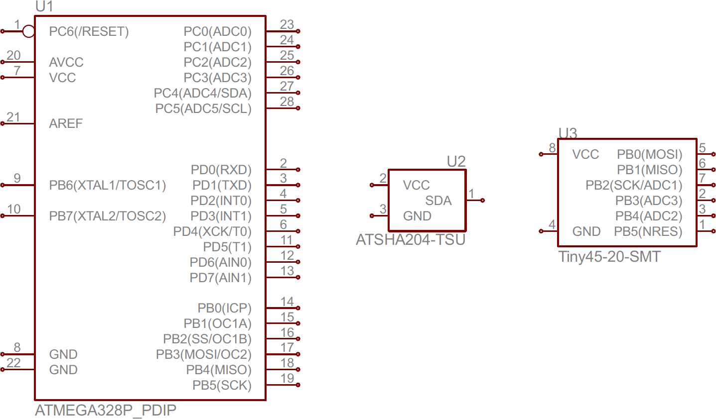
Circuit notation and reference designators.
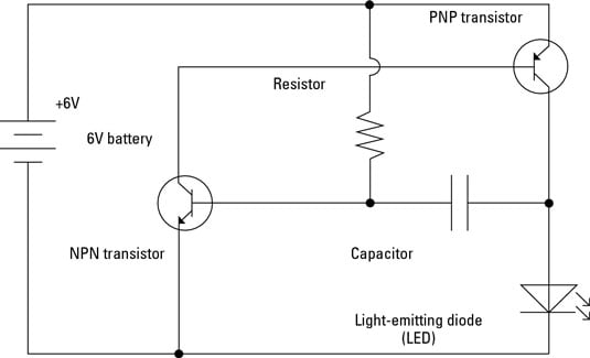
Circuit diagram abbreviation. 5 ways to abbreviate circuit updated 2019. A pictorial circuit diagram uses simple images of components while a schematic diagram shows the components of the circuit as simplified standard symbols. A 4 how to read the wiring diagrams how to read circuit diagrams how to read circuit diagrams the circuit of each system from fuse or fusible link to earth is shown. Key components for base stations a freely programmable formula database can be used to determine equivalent circuit diagrams calculate air gap or cogging torques for motor analysis plus calculation for space vector part transformation and thd to analyze inverter behavior.
Both are quite similar to each other although there are a number of differences. When developing a circuit diagram or schematic it is necessary to identify the individual components. Both types show the connections between the devices including power and signal connections. Circuit diagram a circuit diagram is a simplified conventional graphical representation of an electrical circuit.
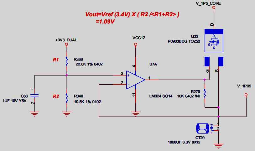
Figure 6 shows the small signal equivalent circuit diagram of a junction varactor. However as many circuit diagrams are used globally both systems will be well known to most electronics engineers. The power supply is shown at the top and the earth at the bottom to facilitate understanding of the current flow.

Circuit Diagram Wikipedia

Circuit Wiring Electrical System W220 S Class Encyclopedia

Electronic Components Name Abbreviations And Symbols List

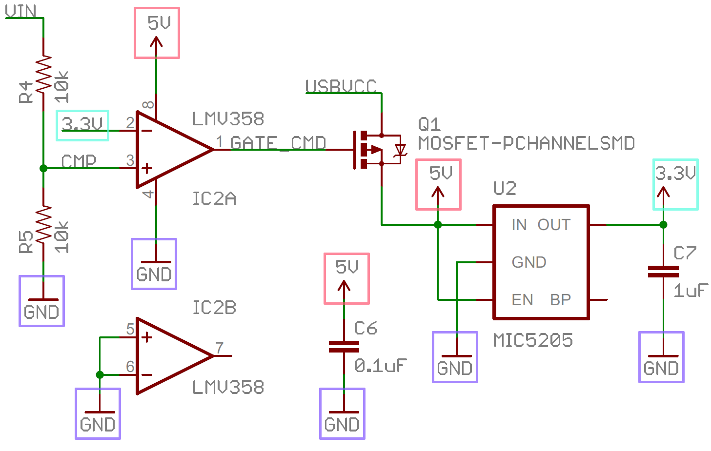
How To Read A Schematic Learn Sparkfun Com
Electronics Schematics Commonly Used Symbols And Labels

Village Electrification Part 3 Electrical Control Systems

Village Electrification Skat 1992 128 P Part 3

Electronic Components Name Abbreviations And Symbols List
How To Read A Schematic Learn Sparkfun Com

Electronic Diagram Symbols And Abbreviations Nilza Net

Schematic Diagram Of Study Design Abbreviations Ckd 828 80

Circuit Nomenclature Symbols

Medical Abbreviations And Symbols Click The Image To Open
How To Read A Schematic Learn Sparkfun Com

Circuit Diagram Wikipedia

Schematic Diagram Of The Compact Sampler Abbreviations In

Schematic Diagram Of Ol Hdf Abbreviation Art Arterial

U Integrated Circuit Circuit Diagram Marking
