Garmin Gp Wiring Diagram
Garmin Gps To Pc Wiring Instructions Introduction This Will
Garmin 250 Wiring Diagram Wiring Schematic Diagram

Gps Swannanoa

Gps 17x gfs.
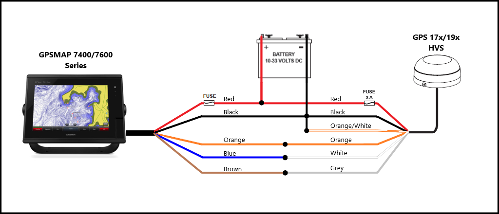
Garmin gp wiring diagram. Within this period garmin will at its sole option repair or replace any components that fail in normal use. To ensure the best reception mount the gps 17 in a location that has a clear unobstructed view of the sky in all directions. Connecting the wiring harness to power. B page 2 12 limited warranty this garmin product is warranted to be free from defects in materials or workmanship for one year from the date of purchase.
About the wiring harness. Pinout of garmin nuvi gps power connector and layout of 5 pin mini usb plug connectorwiring diagram pinout to place garmin nuvi oregon and gpsmap 62 gps in recharge mode. Lamp or horn connections. Gps gns 530 gps pdf manual download.
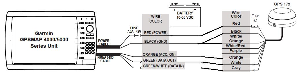
Connecting the device to a transducer. You can hardware your garmin handheld or nuvi to your vehicle with the appropriate garmin usb bare wire power cable from gps city. This video will show you the two best options for powering your unit. Gpsmap 400500 series installation instructions 3 installing a transducer consult the chartplotter feature matrix on page 1 to determine if your chartplotter is capable of using sonar.
If two or more gpsmap 2006c2010c units are installed only one gps 17 needs to be installed. The rst diagram on the next page shows the gpsmap 3006c3010c mfd using the 18 pin powerdata wiring harness and the gps 17. Nmea 0183 connection considerations. 190 00885 07 gps 17x hvs technical specifications rev.
Technical reference for garmin nmea 2000 products iii introduction. The following transducer installation procedures are only applicable to sonar capable chartplotters. Radar sonar and map sharing considerations. Garmin gps to pc wiring instructions introduction this will outline the basics for connecting most garmin gps receivers to a pc serial connector for data transfer.
View and download garmin gps gns 530 installation manual online. The gps 17 connects to the 18 pin powerdata cable on the gpsmap 2006c2010c and provides the gpswaas signal for the unit. Transmit data txd receive data rxd and signal ground sg. 151 street olathe.
Since the gps needs to both send and receive information from your pc the data connection will consist of three wires. A diagram on the product box shows which nmea 2000 components are included. Sample box diagram gfs 10 in the sample box diagram a complete nmea 2000 network is shown and the parts included with the sensor are shaded. If two or more gpsmap 3006c3010c units are installed and networked only one gps 17 antenna needs to be installed.
Page a 4 rev g gps 500 airborne gps system 010 00176 which includes 011 00562 tso c129a class a 1 gps garmin international inc.
Garmin Gps To Pc Wiring Instructions Introduction This Will
Wiring Garmin 4212 To Gps 17hvs The Hull Truth Boating

Garmin 441s Gps Wiring Diagram Wiring Library

Diagrams For Connecting Bare Wire Of Gps Nmea 0183 To

Boat Project Com A Tutorial On Making A Basic Nmea 0183
Garmin 19x To Garmin 5212 The Hull Truth Boating And
Crappie Com America S Friendliest Crappie Fishing Community

Working With Garmin Receivers Accessories
Garmin Gps Wiring Diagram Wiring Library

Working With Garmin Receivers Accessories

Diagrams For Connecting Bare Wire Of Gps Nmea 0183 To
Nmea Wiring Issue With Garmin 541s And Uniden Um380 Page 1

Boat Project Com A Tutorial On Making A Basic Nmea 0183

I Was Given A Garmin Gpsmap 168 Sounder The Power Cord

Marine Navigation

Garmin Wiring Diagram 17 Wiring Diagram

Garmin 441s Gps Wiring Diagram Wiring Library

Garmin Samsung Charger Reverse Engineering 5 Steps With
