Honda Civic Tp Wiring Diagram
1996 1998 Throttle Position Sensor Circuit Diagram 1 6l Civic
The Official Honda Tps Wiring And Calibration Thread Honda
1992 Honda Civic Tps Wires 1992 Honda Civic I Have A 92
Wiring diagrams honda.
Honda civic tp wiring diagram. And then accustom yourself the tps consequently that the idl fasten is continuous to the e2 fix next the throttle is closed and entre circuit taking into consideration. Obd2b engine harness w obd2a or obd1 ecu tach wiring fix. 94 95 acura integra gsr b18c1 vacuum diagram. Page 1 of 2.
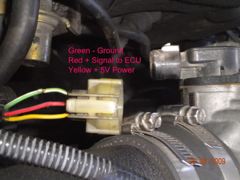
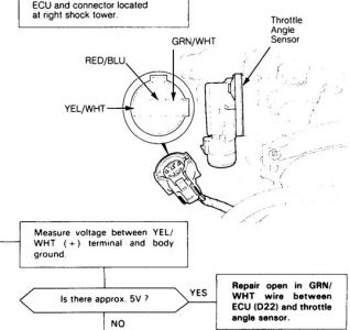
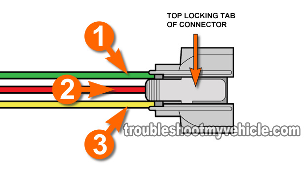
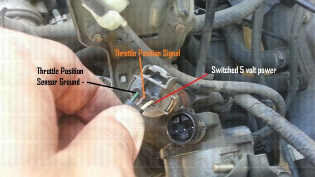
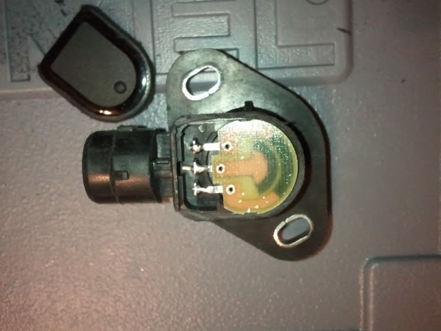
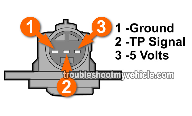
Autozone repair guide for your wiring diagrams wiring diagrams wiring diagrams 1 of 30. To create sure the throttle plate is 100 closed and not slightly stuck with carbon. Checking the throttle position sensor tps signal with a multimeter. How to test the tp sensor 2001 2005 honda 17l.
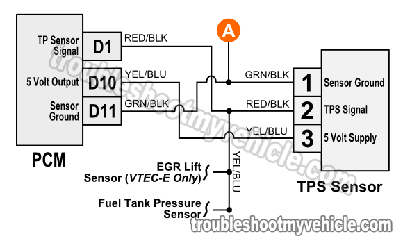
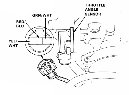
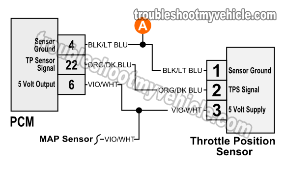
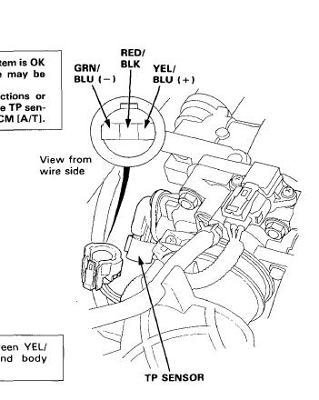
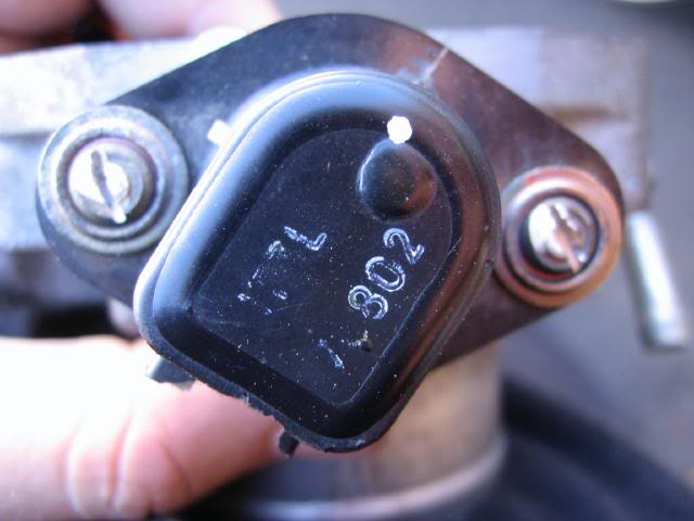
The throttle position sensor tps wiring diagrams and info in this page apply only to 1997 1998 16l honda civic. If you run into an electrical problem with your honda you may want to take a moment and check a few things out for yourself. Honda civic wiring diagram 2004. Homepage autowiring honda civic wiring diagram 2004.
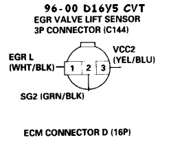
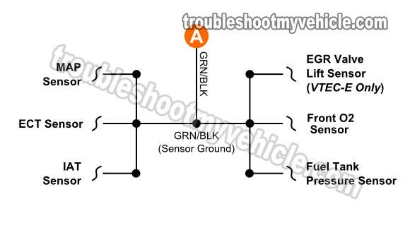
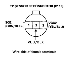
The pcm provides 5 volts dc on the yelblu wire to both the throttle position sensor fuel tank pressure sensor and the egr valve lift sensor on vtec e only. Before you dive in with a multi meter you will want to obtain a free wiring diagram for your specific modelyou may need to locate a specific color wire and its exact location. Throttle position sensor tps wiring diagram. 88 91 honda civic crx b16a vacuum diagram without dashpot valve 90 91 acura integra b18a1 vacuum diagram with dashpot valve 92 93 acura integra b17a1 vacuum diagram.
1996 1998 Throttle Position Sensor Circuit Diagram 1 6l Civic
Part 1 How To Test The Throttle Position Sensor Honda 1 6l
92 00 Honda Acura Engine Wiring Sensor Connector Guide
Honda Tps Wiring Wiring Schematic Diagram

Pin On Auto Electrical
How To Service Your Civic Throttle Position Sensor Dtc P1121
The Official Honda Tps Wiring And Calibration Thread Honda

Honda Tps Wiring Wiring Diagram

Wrg 5771 Honda Tps Wiring
Part 1 How To Test The Throttle Position Sensor Honda 1 6l
Honda Tps Wiring Diagram Wiring Schematic Diagram
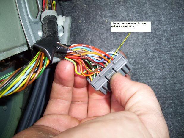
Diy How To Calibrating The Voltage On Your Tps Sensor
Honda Civic Tps Wiring Diagram Wiring Diagram

Honda Tps Wiring Wiring Schematic Diagram
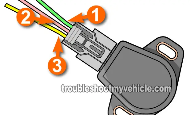
Part 1 How To Test The Tp Sensor 2001 2005 Honda 1 7l
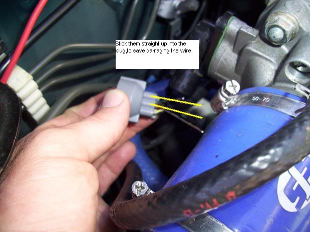
Diy How To Calibrating The Voltage On Your Tps Sensor

Honda Tps Wiring Wiring Schematic Diagram
The Official Honda Tps Wiring And Calibration Thread Honda
