Proces Flow Diagram Water Treatment

In the conventional hierarchy of sewage treatment.
Proces flow diagram water treatment. Types of membrane housing in ro skid. The heavy particles floc settle to the bottom and the clear water moves to filtration. Tertiary treatment process broadly involves the removal of suspended and dissolved solids nitrogen phosphorus and pathogenic organisms. These are existing industrial water treatment systems they can be sized from 10 gpm to 250 gpm.
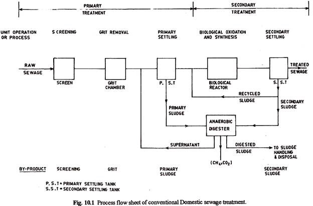
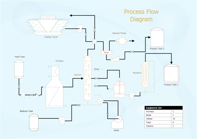
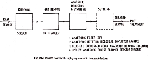
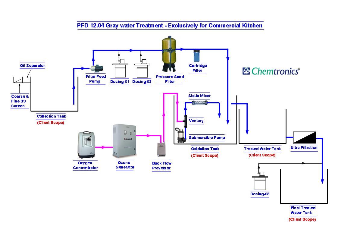
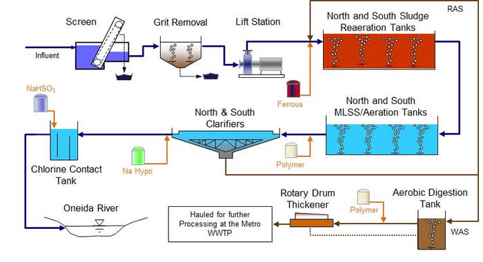
Share discover and update pfd templates in the professional content sharing community. With edraw max you can edit the free pfd template for personal and commercial use. Industrial water treatment systems process flow diagram. The process flow sheet or flow diagram is a graphical representation of the sequence in which various unit operations and unit processes are adopted for treatment of sewage at any sewage treatment plant.
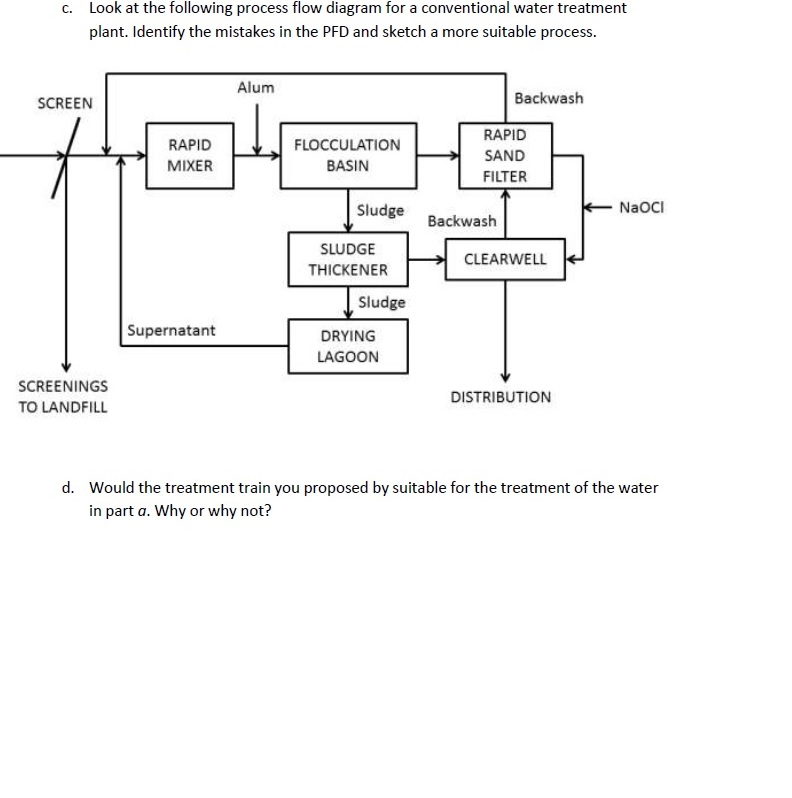
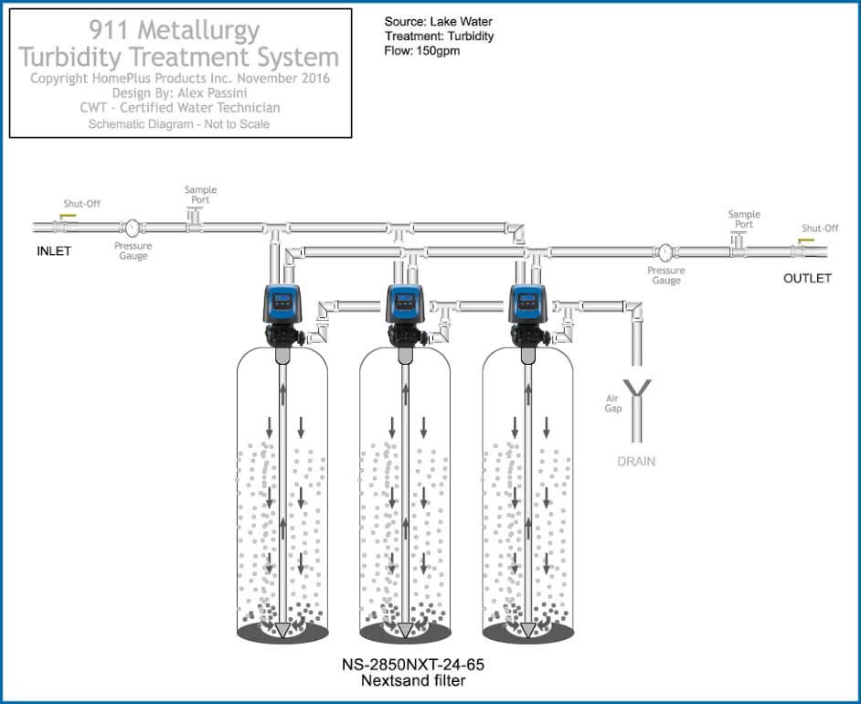
The water must be pretreated coagulated and flocculated before passing through the filter bed. Drinking water treatment process flow diagram. For the removal of nitrogen and phosphorus compounds. Oil refining isomerization 1.
Text in this example. Such high rate direct filtration processes are widely applied to raw water with low levels of suspended matter. Particles at higher water flow rates. Create process flow diagram examples like this template called drinking water treatment process flow diagram that you can easily edit and customize in minutes.
However tertiary treatment is needed under the following circumstances. We can install membrane housing in ro skid with. Oil refining hydrodesulphurization. Process flow diagram for aspropyrgos water treatment plant 46485840674 flow chart of water treatment plant with 37 similar files.
Browse process flow diagram templates and examples you can make with smartdraw. Ro water treatment plant reverse osmosis plant simple process ro water treatment plant process. Water is placed in a closed tank or reservoir for disinfection to take place. Oil industry process flow diagram.
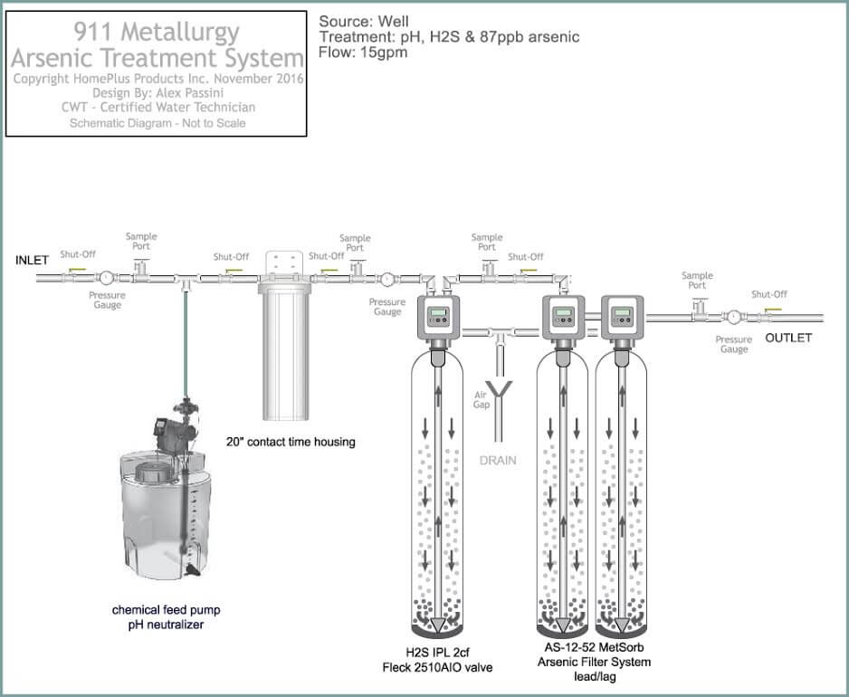
Posted by water treatment in water treatment 19 responses. Flow diagram of reverse osmosis plant. At 25 ppb as i can run a system at 40 gpm however at 120 ppb as i need to reduce it down to 10 gpm with the same system to increase contact time.


