Simple Mobile Charger Circuit Diagram

Usb Cellphone Charger Circuit

Simple 12 Volt Charger Circuit

Usb Mobile Charger Circuit Circuit Diagram Circuit Usb

Components description of battery charger circuit.
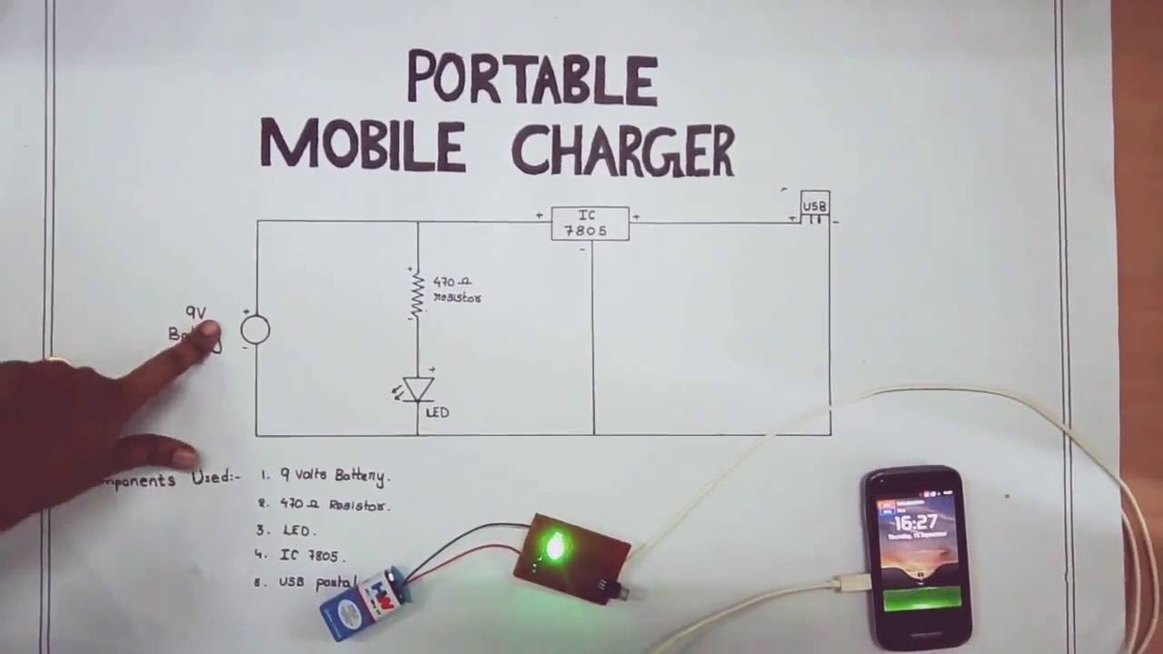
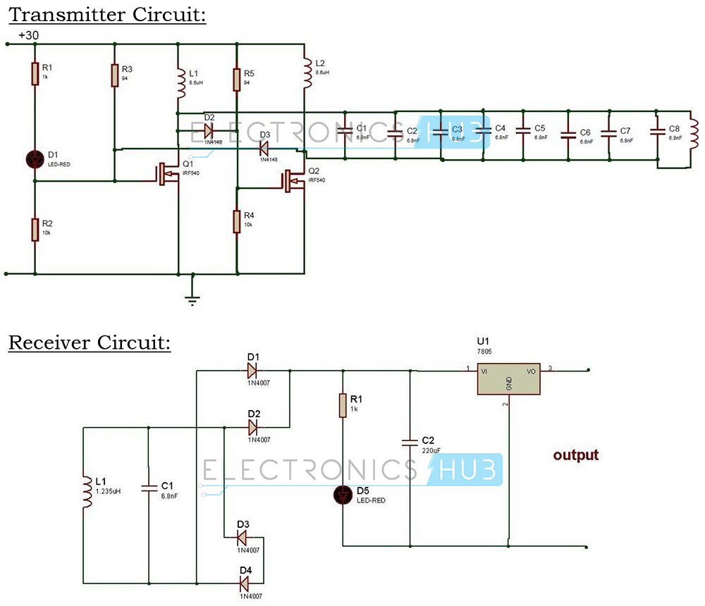
Simple mobile charger circuit diagram. These circuits require only resistors capacitors diodes voltage regulator copper coils and transformer. Finally the part list you can replace most of them by their closest alternative. Transmitter circuit for wireless mobile charger circuit diagram. We can divide this circuit into four parts.
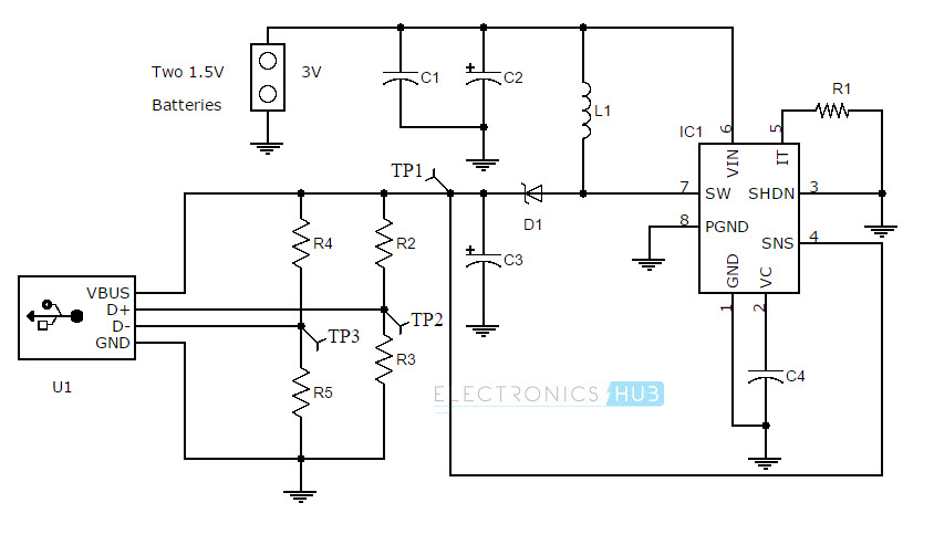
It is a step up dcdc converter by linear technology. Normally a dc cell phone charger circuit come as an integral part of a cell phone package and we use it in conjunction with our ac mains supply. Portable mobile phone charger using boost converter circuit diagram. Part list of the mobile charger circuit.
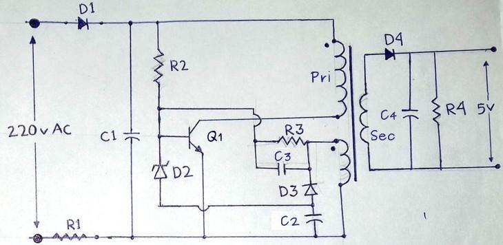
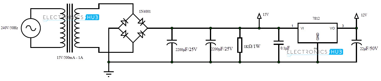
1 step down ac voltage 2 rectification 3 filtration 4 voltage regulation. It use lm78xx regulator to make regulated and stable output voltage. Cell phone charger circuit. A simple dc cell phone charger circuit is one of those mates of cell phone that cannot be ignored because a cell phone would be dead without a charger.
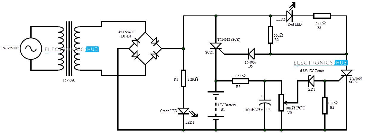
The circuit uses a 0 14 volt 5 ampere step down transformer and a 10 amps bridge rectifier module to convert ac to dc. Wireless battery charger circuit design is very simple and easy. Battery circuit diagrams lcd led display mobile phone circuit diagrams no comments print email. D3 1n4148 diode.
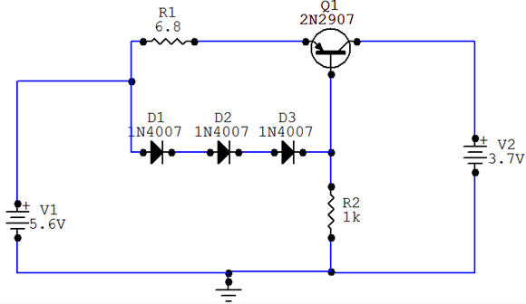
The transmitter circuit of wireless mobile charger circuit diagram is shown in figure 1 and is built around timer ic 555 a general purpose npn transistor bc547 n channel mosfet irf540n lc tuned circuit and a 5 volt series voltage regulator 7805. R1 68 ohm 12 watt. D4 sb260 schottky diode. Nowadays mobile phones have become an integral part of everyones life and hence require frequent charging of battery owing to longer duration usage.
June 17 2018 in. The first circuit is transmitter circuit used to produce voltage wirelessly. Wireless mobile charger circuit design. The input voltage can be as low as 2v and the output current can be up to 600ma.
Q1 13001 transistor. The following diagram is a simple mobile phone battery charger circuit. This circuit mainly consists a step down transformer a full wave bridge rectifier and a 5v voltage regulator ic 7805. D1 1n4007 diode.
D2 62v zener diode. This is the circuit of a simple 12 volt battery charger for lead acid battery. If the battery is partially discharged full charge will be attained in one hour. In our wireless battery charger we use two circuits.
A mobile battery charger circuit is a device that can automatically recharge a mobile phones battery when the power in it gets low. Mobile phone chargers offered in the marketplace are quite expensive.

Simple 12 Volt Battery Charger Circuit Diagram
Portable Mobile Charger Circuit Diagram
Automatic 12v Portable Battery Charger Circuit Using Lm317
Battery Charger Circuit Make A 12v Battery Charger At Home

Mobile Charger Circuit Diagram 100 220v Ac Circuits Diy
Simple Mobile Phone Battery Charger Circuit Scheme
Mobile Charger Circuit Diagram 100 220v Ac Circuits Diy
Automatic 12v Portable Battery Charger Circuit Using Lm317
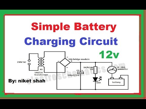
Simple Battery Charging Circuit In Hindi By Niket Shah

Mobile Phone Travel Charger

Wireless Mobile Charger Circuit Diagram Engineering Projects
Wireless Power Transfer Circuit Wireless Mobile Charger

220v Smps Cell Phone Charger Circuit Homemade Circuit Projects

Automatic Battery Charger Circuit

How To Build Nicd Battery Charger Circuit Diagram Battery
12v Battery Charger Circuit Diagram Using Lm317 12v Power
Scematic Diagram Battery Charger Booster Circuit Diagram
Simple Auto Turn Off Battery Charger Power Electronic
